


Fundamental Differences in PV Laser Grooving Parameters Between PERC and TOPCon Architectures
Thermal and Ablation Threshold Variations Across Al-BSF vs Poly-Si Passivation Stacks
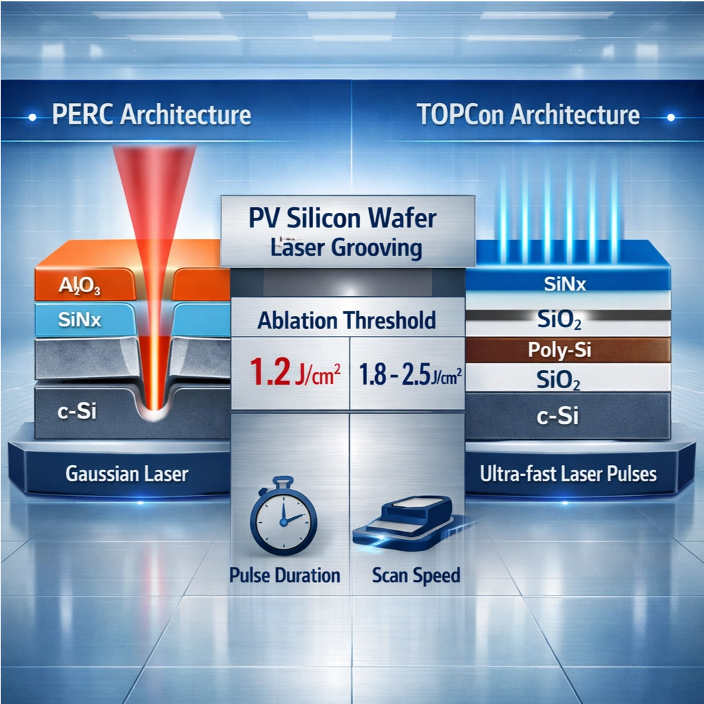
PERC cells have what's called an aluminum back surface field (Al-BSF) with a pretty uniform rear contact structure. This setup allows for fairly predictable interactions when lasers are used on the material, typically around an ablation threshold of about 1.2 J per square centimeter. Things get different with TOPCon technology though. The tunnel oxide layer combined with polycrystalline silicon (poly-Si) creates a much more complicated situation where thermal conductivities vary across layers. Because poly-Si handles heat better, we see ablation thresholds jump up to somewhere between 1.8 and 2.5 J per square cm. Getting the right amount of energy applied here matters a lot. Too much power will actually crack those poly-Si layers, but not enough leaves behind unwanted oxide residue. And for standard PERC cells, going over approximately 1.5 J per square cm can lead to problems like aluminum splattering and electrical shorting issues.
Impact of Layer Stack Complexity on Groove Edge Quality and Recombination Risk
The complex five layer structure of TOPCon (SiNx over SiO2 then poly-Si followed by another SiO2 layer on c-Si) creates much higher risks of edge recombination when grooving compared to the simpler three layer setup used in PERC technology (Al2O3/SiNx/c-Si). When thermal energy spreads unevenly through those poly-Si layers during processing, it actually leads to tiny cracks forming around 3 to 5 micrometers past the groove edges. These defects boost surface recombination rates by about 40% more than what's seen with PERC cells. To fix this problem, manufacturers need extremely fast laser pulses under 10 picoseconds to keep heat damage localized. With PERC technology, there's another issue entirely - if the angle at which grooves are cut goes above 70 degrees, it tends to create gaps in the metal coating that drops cell efficiency somewhere around 0.8%. That means solar panel makers have to tailor their laser grooving techniques based on the specific cell architecture they're working with. TOPCon generally works best with multiple laser pulses spread out over time to handle thermal stresses better, whereas PERC cells typically produce smoother edges when processed with Gaussian shaped laser beams.
Defining the Robust PV Laser Grooving Process Window
Critical Parameter Trade-offs: Pulse Duration, Fluence, and Scan Speed for Depth Uniformity (±0.3 μm)
Getting depth uniformity within ±0.3 μm depends heavily on finding the right balance between pulse duration, fluence levels, and how fast we move across the material. When working with shorter pulses in the range of 10 to 50 nanoseconds, we get smaller heat affected areas but need to crank up the fluence to around 2 to 5 joules per square centimeter for proper ablation results. On the flip side, longer pulses transfer energy better but can actually damage those delicate passivation layers through excessive heating. The scan speed has to match up closely with our chosen fluence settings too. Going over 5 meters per second tends to create tapered grooves, whereas anything under 2 m/s usually leads to annoying microcracks forming in the material. From what most manufacturers see in their day-to-day operations, bumping the fluence by about 0.5 J/cm² lets them scan roughly 15% quicker without sacrificing depth control. Something worth noting is that keeping pulse spatial overlap under 30% helps avoid heat accumulation problems. This makes all the difference when comparing PERC versus TOPCon technologies since those poly-Si layers need about 40% more energy before they start ablating compared to traditional Al-BSF structures.
Single-Pass vs Multi-Pass Grooving: Yield, Throughput, and Edge Isolation Stability Trade-offs
| Parameter | Single-Pass | Multi-Pass |
|---|---|---|
| Throughput | High (8–12 wafers/min) | Moderate (4–6 wafers/min) |
| Edge Isolation | ±15% leakage current variance | ±5% leakage stability |
| Yield Impact | 3–5% lower due to debris | >98% with controlled redeposition |
| Thermal Management | Challenged at >1 kW power | Optimized through energy staging |
When using single pass grooving techniques, manufacturers get maximum throughput but run into problems with uneven edges and silicon debris buildup. This becomes really troublesome for those working with TOPCon's complicated poly-Si/SiOx layer structures. Going the multi-pass route helps out quite a bit since it spreads out the energy application over several steps. This approach brings down peak temperatures around 60 degrees Celsius and makes those edge isolations much more stable. Still worth noting though, there's about a 50% hit to production speed which means companies need to do some serious cost benefit calculations before switching. Research from last year showed that multi-pass methods only make financial sense if cell efficiencies are pushing past 24%. For PERC wafers specifically, many plants have adopted hybrid strategies where they start with a strong initial pass then follow up with gentler cleaning passes. These combinations typically hit around 96% yield while processing about seven wafers per minute. At the end of the day, anyone optimizing their manufacturing process should focus heavily on preventing edge recombination issues because even small losses here translate directly into efficiency drops. Just 1% less isolation equals roughly 0.3% lower overall performance, something no manufacturer wants to see on their bottom line.
Validating and Measuring PV Laser Grooving Parameters in High-Throughput Production
In-Line Metrology Comparison: OCT vs Confocal Microscopy for <±50 nm Groove Depth Uncertainty
Getting depth measurements below 50 nanometers in mass production requires some serious in-line measurement tech these days. Optical Coherence Tomography or OCT does pretty well here, offering fast non-contact 3D imaging capabilities that can handle around 200 wafers per hour. That makes it a good fit for those high volume PERC and TOPCon production lines we see everywhere now. The way OCT works with interference patterns lets it pick up those tiny depth changes down to microns, although it starts to struggle when dealing with really steep walls over 80 degrees. On the other hand, confocal microscopy takes a different approach using pinhole filtered lasers to scan surfaces. This method actually provides better vertical resolution, verified at plus or minus 20 nanometers, particularly useful for complicated groove shapes. It's not as fast though, cutting production speed down about 30%, but what it gains in detail makes up for it. Confocal systems spot those pesky micro cracks and leftover ablation material that can cause problems later on in silicon passivation layers. When manufacturers need to balance how fast they go against how accurate they need to be, OCT tends to work best for shallow features under 3 micrometers deep. But for deeper structures in TOPCon designs where heat damage is a big concern, most experienced engineers will reach for confocal microscopy instead.
FAQs
What is the main difference between PERC and TOPCon cell technologies?
PERC cells utilize an aluminum back surface field (Al-BSF) structure, while TOPCon cells incorporate a more complex layer that includes polycrystalline silicon (poly-Si) and tunnel oxide, allowing for higher ablation thresholds but also adding complexity in the process.
Why is laser grooving important in photovoltaic cell production?
Laser grooving is crucial for precise cutting of layers in solar cell manufacturing, impacting efficiency, edge quality, and recombination risk, thereby influencing the overall performance of the cells.
How does pulse duration affect the grooving process?
Pulse duration plays a significant role in controlling heat affected areas and depth uniformity. Shorter pulses minimize heat distribution while requiring higher fluence for effective ablation, whereas longer pulses can cause excessive heat buildup, damaging delicate layers.
What advantages do multi-pass grooving techniques offer?
Multi-pass grooving techniques spread out energy application, decreasing peak temperatures and enhancing edge isolation stability. However, they reduce production speed, requiring cost-benefit analysis to determine financial viability.
How are OCT and confocal microscopy used in production line measurement?
OCT provides fast, non-contact 3D imaging for shallow features, suitable for high throughput settings. Confocal microscopy offers higher resolution for complex shapes and detects microcracks, although at a slower pace, beneficial for detailed inspection in complex layer structures.
Table of Contents
- Fundamental Differences in PV Laser Grooving Parameters Between PERC and TOPCon Architectures
- Defining the Robust PV Laser Grooving Process Window
- Validating and Measuring PV Laser Grooving Parameters in High-Throughput Production
-
FAQs
- What is the main difference between PERC and TOPCon cell technologies?
- Why is laser grooving important in photovoltaic cell production?
- How does pulse duration affect the grooving process?
- What advantages do multi-pass grooving techniques offer?
- How are OCT and confocal microscopy used in production line measurement?