


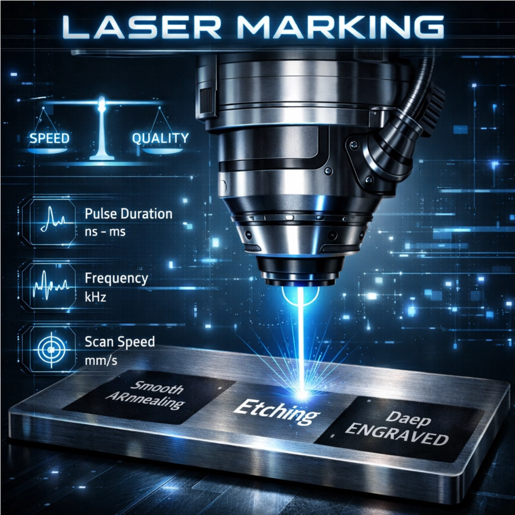
The Core Speed–Quality Trade-Off in Laser Marking
The relationship between speed and quality in laser marking works kind of backwards actually: when things go slower, there's better control over how deep the mark goes into materials. But crank up the speed too much and the laser doesn't stay in contact long enough to create good contrast or consistent depth. Take medical devices for example. Getting those tiny marks around 0.005 inches deep usually means running several fast passes instead of one super slow one. It's all about finding that sweet spot between getting work done quickly and keeping the marks sharp and clear. On the flip side, super fast marking at rates like 2000 mm per second creates just skin deep etchings great for putting batch codes on packaging materials. However this approach can leave problems with reflective metals such as aluminum where the oxidation process might not complete properly. Different materials react differently to these settings too. Stainless steel handles higher power levels pretty well for creating dark annealed marks at medium speeds. Copper though? That stuff needs really careful timing of the laser pulses to avoid splattering, even when going at 700 mm/s. According to numbers we saw from the Laser Institute of America back in 2023, almost two thirds of all marking issues come down to mixing up the right speed with the wrong material type. So yeah, getting this balance right matters a lot if manufacturers want both productivity and quality marks on their products.
Material-Specific Parameter Optimization for Laser Marking Speed and Quality
Stainless Steel: Balancing Power, Pulse Duration, and Scan Speed for High-Contrast Annealing
Getting good laser marks on stainless steel depends on getting three main factors just right. If the laser has too much power, it burns off carbon and makes the mark look washed out. Not enough power means longer processing times but still poor quality marks. For pulse durations, anything under 100 nanoseconds helps control heat buildup but might not create a proper oxide layer. Going over 150 ns tends to spread heat too much throughout the material. When it comes to scan speed, pushing past 2,000 mm per second definitely boosts production rates but creates inconsistent depths, particularly noticeable on curved or textured parts. Studies indicate that matching pulse length to how fast heat moves through 304 grade steel around 150 ns or less can cut processing time by about 30%. To get those sharp, high contrast marks with optical density above 0.8, operators should cap peak power at no more than 80% of what the machine can do and space hatch lines closer than 0.05 mm apart. With these adjustments, most shops report reliable results in about 1.5 seconds per mark.
Aluminum & Titanium: Tuning Frequency, Focal Offset, and Peak Power to Counter Reflectivity and Thermal Spread
The high reflectivity of aluminum surfaces can reach about 90%, while titanium conducts heat very quickly, so we need specific approaches when using lasers on these materials. Adjusting the focal point by around 1.5 to 2.5 millimeters actually makes the laser beam spread out more. This helps distribute the energy across the surface better, which tackles the reflectivity problem without causing vaporization issues or those tiny cracks that sometimes form. When it comes to frequency settings, there's a range from 50 to 200 kilohertz that works well. For example, if working with thin titanium parts about half a millimeter thick, going up to 200 kHz is usually best. But for thicker aluminum pieces used in aerospace applications at around three millimeters, sticking closer to 100 kHz tends to produce better results. The peak power needs to be strong enough to get past what's called the ignition threshold, typically above 70%, but not so intense that it starts ablating the material. Shaping how the laser pulses also plays a role in keeping the molten area stable during processing, which reduces unwanted edge distortions. Looking at the data in our comparison table shows exactly how these carefully set parameters affect things like halo formation around marks, overall marking width, and whether parts end up with insufficient markings after processing.
| Parameter | Aluminum Range | Titanium Range | Quality Impact |
|---|---|---|---|
| Frequency | 100–150 kHz | 150–200 kHz | Reduces halo effect |
| Focal Offset | +1.0–2.0 mm | +1.5–2.5 mm | Controls mark width |
| Peak Power | 60–75% | 70–85% | Prevents under-marking |
Copper & Brass: Controlling Oxidation and Melt Splatter via Hatch Spacing, Pulse Shaping, and Duty Cycle
Working with copper and brass presents unique challenges because these metals conduct heat so well and tend to oxidize uncontrollably when marked. Getting hatch spacing right matters a lot. If it goes over 0.12 mm, the marking just doesn't cover properly and looks faded. But go below 0.08 mm and things get messy with overlapping melt areas and rough surfaces. The good news? A gradual increase in pulse intensity helps reduce thermal shock, which cuts down on splatter by around 40%, according to recent metallurgy research. Keeping duty cycles under 30% gives enough time between pulses for cooling, which stops oxidation from happening. When dealing specifically with brass, setting Q-switch frequencies between 80 and 120 kHz while keeping pulse widths under 120 nanoseconds produces clean marks without any zinc separation issues. This lets manufacturers achieve flawless identification marks even at high speeds of 1,800 mm per second. Such precise control isn't just nice to have for electronics tracking but absolutely necessary since both readability of marks and maintaining material quality simply cannot be compromised.
Marking Technique Selection to Maximize Laser Marking Speed Without Compromising Quality
Annealing vs Etching vs Engraving: Depth, Contrast, and Throughput Implications
How we mark materials really affects what we get in terms of speed versus quality. Take annealing for instance. This method applies controlled heat to create those nice subsurface oxide layers that give us these high contrast marks which resist corrosion too. Think about how stainless steel turns black or titanium gets that golden look without actually taking away any material from the part itself. It might take around half as long as other methods like etching or engraving, but what it loses in speed it gains in preserving both the structure and surface finish of the component. That's why doctors rely on this technique when making medical implants and engineers trust it for critical aerospace parts where surface integrity matters most. Etching works differently by basically burning off tiny bits of the surface layer, usually between 1 to 5 micrometers thick. This gives pretty sharp, detailed codes fast enough for things like electronic components or product packaging. But watch out if working with shiny surfaces or metals that conduct heat well because etching just doesn't work so great there. Then there's engraving, which takes a much more aggressive approach. It blasts away material at depths ranging from 10 up to 200 micrometers using powerful laser pulses. While this definitely delivers the fastest results possible, it comes with problems like melt splatter and rough edges, especially noticeable when dealing with softer metals such as copper or brass.
| Technique | Depth | Contrast | Throughput | Best Use Cases |
|---|---|---|---|---|
| Annealing | Subsurface | High | Low–Moderate | Medical implants, aerospace |
| Etching | Shallow (1–5µm) | Moderate–High | Moderate–High | PCBs, consumer electronics |
| Engraving | Deep (10–200µm) | Variable | Highest | Industrial tools, automotive |
Prioritize annealing for mission-critical, corrosion-sensitive applications. Choose etching for high-volume alphanumeric or barcode marking where surface integrity is secondary to speed. Reserve engraving for deep, permanent identifiers on robust substrates where edge definition is less critical than durability.
Laser Source Alignment with Material and Speed–Quality Goals
Choosing the correct laser isn't something to leave until last minute decisions. Fiber lasers ranging from 1000 to 6000 watts have become the go to option for metal marking thanks to their excellent beam quality measured at M squared values below 1.1. These lasers produce focused stable energy that works great for fast annealing processes on stainless steel surfaces and creates very detailed markings on titanium parts. The reason? Their wavelength sits around 1064 nanometers which interacts well with most types of metal, so there's less energy lost through reflection issues. On the flip side, CO2 lasers operating at about 10.6 micrometers wavelength perform better when working with plastics, ceramic components, or materials with special coatings since those longer waves get absorbed more effectively. But try using them on plain metals without any coating and things don't work out so well because of all the bouncing off and poor connection between laser and material.
Mismatched sources introduce avoidable failure modes: overpowered fiber lasers on thin aluminum cause burring and warping; underpowered CO2 systems on copper produce faint, inconsistent marks. Three calibration levers determine success:
- Peak Power: Must be tuned to material ablation thresholds—higher settings accelerate marking but trigger splatter on brass if not paired with pulse shaping.
- Beam Focus: Ultra-fine spots (≈0.02 mm) enable micron-level detail but demand ±0.03 mm positioning accuracy—critical for micro-electronics serialization.
- Pulse Control: Frequencies >2,000 Hz maintain line continuity during high-speed vector marking, preventing fragmentation in fine fonts or barcodes.
Manufacturers who get their laser specs right for specific materials see around 30% improvement in processing speed. When the laser matches what the material can absorb and meets quality standards, things just work better. Take titanium parts for instance. Pulsed fiber lasers help avoid oxidation issues, whereas continuous wave CO2 lasers handle acrylic nameplate engraving pretty well. But here's something important most people overlook. Real validation needs to happen on actual parts from production runs, not those little test samples everyone keeps using. Companies that document their successful parameters in databases that are easy to search and track versions over time cut down setup times roughly half. This makes all those nice theoretical speed vs quality calculations actually useful in practice, turning them from abstract ideas into consistent outcomes across different batches and projects.
FAQ Section
What is the speed-quality trade-off in laser marking?
The trade-off refers to the balance between marking speed and the quality or depth of marks. Slower speeds generally allow better control for deeper marks, while faster speeds prioritize quick production with more superficial markings.
How do different materials react to laser marking?
Materials respond differently to laser marking settings. Stainless steel can handle higher power levels for dark marks, while copper requires precise laser pulse timing to avoid splattering. Aluminum's reflective surface needs specific frequency and focus adjustments.
What techniques are used in laser marking?
Laser marking techniques include annealing, etching, and engraving, each with its specific depth, contrast, and speed benefits, tailored to different applications and material needs.
How important is laser source alignment?
Laser source alignment is crucial for effective marking. Fiber lasers are preferred for metals due to their stable energy and wavelength, while CO2 lasers are effective for plastics and ceramics. Proper alignment prevents inaccurate marks and enhances material absorption.
Table of Contents
- The Core Speed–Quality Trade-Off in Laser Marking
-
Material-Specific Parameter Optimization for Laser Marking Speed and Quality
- Stainless Steel: Balancing Power, Pulse Duration, and Scan Speed for High-Contrast Annealing
- Aluminum & Titanium: Tuning Frequency, Focal Offset, and Peak Power to Counter Reflectivity and Thermal Spread
- Copper & Brass: Controlling Oxidation and Melt Splatter via Hatch Spacing, Pulse Shaping, and Duty Cycle
- Marking Technique Selection to Maximize Laser Marking Speed Without Compromising Quality
- Laser Source Alignment with Material and Speed–Quality Goals
- FAQ Section